C64 Remote Programmer
In this post I will describe a small electronics project designed to enable the remote programming of a real Commodore 64 that is switched on and running. To achieve this, several parts are involed, utilising some custom circuitry and communications protocol, a Raspberry Pi, a C program, a 6502 assembler program and a little F# program to finish it off.
Introduction
Programming the C64 is a lot of fun, and mostly you can get by with using an emulator. However, there comes a time when you wish to run your program on the real machine. To facilitate this, I own a very awesome 1541 Ultimate 2 which mimics the Commodore 1541 floppy drive and allows you to load things from a USB stick. Whilst this is really cool, it is still annoying having to keep moving the program from my main machine to the C64 with the stick to see small changes. The 1541 Ultimate 2 does have an ethernet port which I think you can use to send new code over (not sure how that works, or if it lets you change a running program…), but what I really want is a way whereby I have my program running on the C64, and then when I assemble a new version of the program on my main machine, it magically writes itself over the top of whatever is currently running, and starts executing on the C64 with no hard connection.
High Level Design
The general idea is to connect the C64’s user port to a Raspberry Pi, and design a protocol to transfer data from one to the other. The C64 side will have to include a small assembly program to do this, whilst the Pi will be running a small C program.
The Pi is notified of a new program to send by monitoring a specific directory. The main machine, post-assembly, augments and sends the output file over SCP to the Pi using a small F# program.

Protocol Design
The C64 has a user port which is designed for us to connect our own circuits to. You must be careful, of course! You can easily damage the machine if you are not careful, and I don’t know if my user port even works. The usable part of the port is essentially 10 pins – 8 data pins that form a register you can read at $dd01, and two pins you can use for handshaking with another device. Of these two pins, one is special - the FLAG pin. This pin is input only, and detects negative edges. Upon seeing a logic transition from HIGH to LOW, it sets a bit in the port’s interrupt control register at $dd0d. This bit is cleared when you read the register. If you wish, you can also have it raise a non-maskable interrupt (NMI) enabling you to program with it asynchronously.

The C64’s KERNAL has some routines that use this port to enable RS–232 communication. RS–232 is horribly slow however, being a serial protocol it transmits only a single bit at a time, with the protocol orchestration overhead on top of that. For my purposes, I want something much faster and less general. It doesn’t need to be bullet-proof since it is only for my own use. I would like to use all 8 lines to transfer a whole byte at a time as a parrallel interface.
Of course, the Raspberry Pi is ridiculously faster than the C64, so the top speed will be largely down to how fast the 6502 can process the incoming data. To that end, the C64 side of the programmer aims to do the least amount of work as possible, with hardly any logic and only copying of data.
Low Level
The low-level handshaking and transmission details are as follows
- The Pi signals to the C64 there is a new byte available by cycling the
FLAGline from HIGH to LOW and back again, after writing the bits to the 8 lines. - The C64 loads the data and puts it somewhere, and then inverts the other handshaking line
PA2 - The Pi notices the C64 has finished with the data by polling
PA2, and then sends the next byte.
High Level
The 6502 is very good at copying whole pages of data (256 bytes) since it can use its indexed addressing modes to whip through 256 bytes and easily check when it has finished. The data being sent, however, could be destined for any memory location and be of any length. Therefore, to simplify the job for the C64, we will send it some control bytes about any non-perfectly aligned data as a header, which will be the job of the C program on the Pi to compute.
- 1 : low byte of the location to start executing once programming has finished
- 2 : high byte
- 3 : low byte of the location to being copying data to
- 4 : high byte
- 5 : total amount of full pages of data to copy
- 6 : number of leading bytes that don’t fill a page
- 7 : number of trailing bytes that don’t fill a page
The idea then is for the assembly program to:
- disable interrupts
- create a pointer to the start location
- copy the amount of leading bytes
- repeatedly copy the full pages
- copy the trailing bytes
- enable interrupts, splat the stack
- jump to the execution point
We will see how some of this is implemented later.
Circuit Design
The C64 is of course an old device released back in 1983 (when I was born!) and as such it uses +/– 5v for its logic lines. The Pi is newer and uses the more modern +3.3v for its logic. This means they cannot directly communicate - whilst you can get away with sending 3.3v to a 5v pin, you shouldn’t really, and sending 5v to a 3.3v pin is a definite no!
To solve this problem you’d typically use a level shifter, however, I couldn’t find one in my stuff so instead I decided to solve the problem in another way, by using a transistor switching circuit.
One of the transistor’s primary features is that is able to switch on a larger current / voltage using a very small one. We can use this feature to solve our problem. However, in its most basic configuration, this circuit is also a NOT gate - it inverts the input.
We have 9 of these in total, one for each data pin and one for the FLAG pin. The transistor is switched on using the 3.3v logic, and it ouputs the opposite logic in 5v to the C64.
And one of these for the PA2 handshaking pin from the C64 to the Pi. It is the same, except it is switched on from the C64’s 5v logic and outputs 3.3v.
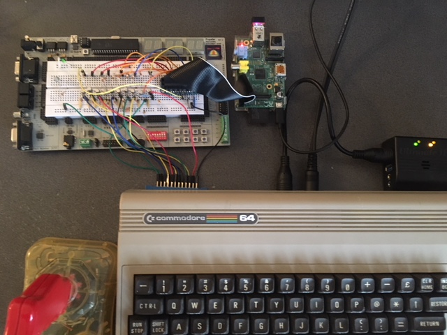
I have kept these diagrams high level since this post is not about the electronics really. I did extensive testing on each part of the circuit and the logic outputs from both devices before putting it all together. The picture below is the Pi’s logic pins driving the transistors and LEDs using a small C program, acting as a binary counter.

Of course, since the circuits invert the logic, the received bytes will be incorrect. We can remedy this by either designing a more complex circuit, or changing how the data is sent / received. It makes sense in this instance to modify how the data is sent since I don’t want to make the circuit more complex and I don’t want the 6502 program to do anything it doesn’t have to.
C Program
The C program’s job is to monitor a directory, and when it sees a new file, send it over the wire. It expects the first four bytes of the file will be the post-programming execution address and address to start writing the data as per the protocol section above (more on how these end up in the file in the final section)
Some of the C program is quite boring, so we’ll look at a couple of the more interesting parts. The library being used here is bcm2835 to control the GPIO pins on the Pi.
1 2 3 4 5 6 7 8 9 10 11 12 13 14 15 16 17 18 19 20 21 22 23 24 25 26 27 28 |
void send_byte(char b) { // write inverted bits bcm2835_gpio_write(PB0, (b & 0x1) ^ 0x1); bcm2835_gpio_write(PB1, ((b >> 1) & 0x1) ^ 0x1); bcm2835_gpio_write(PB2, ((b >> 2) & 0x1) ^ 0x1); bcm2835_gpio_write(PB3, ((b >> 3) & 0x1) ^ 0x1); bcm2835_gpio_write(PB4, ((b >> 4) & 0x1) ^ 0x1); bcm2835_gpio_write(PB5, ((b >> 5) & 0x1) ^ 0x1); bcm2835_gpio_write(PB6, ((b >> 6) & 0x1) ^ 0x1); bcm2835_gpio_write(PB7, ((b >> 7) & 0x1) ^ 0x1); // c64 detects negative edge and sets an interrupt bit // get the current c64 output flag first char pa2 = bcm2835_gpio_lev(PA2); bcm2835_gpio_write(FLAG2, HIGH); // cycle the line low to trigger interrup bcm2835_gpio_write(FLAG2, LOW); // reset again // now wait for the c64 to change its output flag while(bcm2835_gpio_lev(PA2) == pa2) { } return; } |
Here we implement the low level details of the protocol, loading each bit of the byte onto the data lines, inverted so the circuit ends up outputting the correct value. Then it switches the FLAG line and waits for the C64 to respond by inverting PA2, indicating that it has taken the data (ack).
1 2 3 4 5 6 7 8 9 10 11 12 13 14 15 16 17 18 19 20 21 22 23 24 25 26 27 28 29 30 31 32 33 34 35 36 37 38 39 40 41 42 43 44 45 46 |
FILE *fp; fp = fopen(fn,"r"); fseek(fp, 0, SEEK_END); int file_length = ftell(fp); int data_length = file_length - 4; char* data = (char *) malloc(data_length); rewind(fp); unsigned char start_lo = fgetc(fp); unsigned char start_hi = fgetc(fp); unsigned char asm_lo = fgetc(fp); unsigned char asm_hi = fgetc(fp); fread(data, 1, data_length, fp); fclose(fp); int address = (asm_hi << 8) | asm_lo; printf("data load complete. copy address at $%04X.\n", address); // work out how many bytes are on the first page unsigned char first_page_bytes = 256 - (address % 256); int remaining_bytes = data_length - first_page_bytes; // see how many full pages we can fit in int full_pages = remaining_bytes / 256; // and any final stragglers int last_page_bytes = remaining_bytes % 256; //now we can send to the C64! //first send the control data. printf("sending control headers..\n"); send_byte(start_lo); send_byte(start_hi); send_byte(asm_lo); send_byte(asm_hi); send_byte(full_pages); send_byte(first_page_bytes); send_byte(last_page_bytes); for(int i = 0; i < data_length; i++) { send_byte(data[i]); } free(data); remove(fn); |
In this code we extract the first 4 bytes from the file then read the rest into an array. Then we can work out any leading / trailing bytes as per the protocol description, and finally proceed to send the control header followed by the actual data. (this is not the actual code, but close enough - I changed it around to fit in the post)
6502 Program
For the C64 side, we want the program to be as small as possible. Obviously, it needs to fit somewhere inside your program, where you can call it every now and then to see if a new program has arrived. The location it lives should ideally remain static as your program changes, since the programmer will overwrite itself and it had better be in exactly the same place whilst it is doing it!
For now, the perfect spot for this is the area that follows the BASIC program that is executed when the machine first boots. A common machine language trick is to put your own short basic program there, its purpose is to transfer control to your actual program so you don’t have to type in sys 4096 or similar in order to execute your code. This will also become important in the next section with the F# program.
BASIC attempts to execute the program it tries to find at $0801. It expects the program to be in a special format which indicates some stuff to do with line numbers, and the PETSCII (Commodore character set - not the same as ASCII!) text of the BASIC source code to be interpreted. Some details will be glossed over here:
1 2 3 4 5 6 7 8 |
*= $0801 ;autostart (data $0b $08 $01 $00 $9E $34 $30 $39 $36 $00 $00 $00) *= $1000 ; main program ; code here ... |
This is written in my Racket based assembler, Asi64. It is admittedly very cryptic, being simply a bunch of bytes. The first few are to do with the line numbers. $9E is the code for the sys instruction, followed by four bytes which represent in decimal, as PETSCII characters, the address to jump to. In this case, $34 $30 $39 $36 corresponds to 4096 in decimal (subtract $30 from each character) which in turn is $1000 in hex. Finally, the three $00 bytes tell BASIC that the line has ended.
Of course, we can write a nice helper in Asi64 to help us do this like you can in KickAssembler
1 2 3 4 5 |
(basic-upstart $1000) *= $1000 ; code here ... |
The area after the basic program is where we will stuff the remote programmer code. It should be as small as possible, but as long as it fits within the rest of the $0800 page we should be fine. I have not optimised it for space yet, what I present below is the first thing I got to work properly!
1 2 3 4 5 6 7 8 9 10 |
:programmer-check ;interrupt will be set on a negative transition ;indicating the pi has put the first byte of a program ;on the wire lda $dd0d and @%0001_0000 ;if this bit is set then ;jump. reading this also clears it. bne receive-program+ rts |
This function checks the interrupt register, and returns if it has not been set. Using Asi64’s diagnostics reveals this code takes 14 cycles if the branch is not taken, so you can comfortably fit a call into this function somewhere in your program, perhaps once a frame.
1 2 3 4 5 6 7 8 9 10 11 |
:wait ;toggle pa2 to let the pi know we are done lda $dd00 eor @%0000_0100 sta $dd00 ;wait for pi to send a new byte :inner lda $dd0d and @%0001_0000 beq inner- rts |
Next up is this function that waits for a new byte to arrive. First, it toggles the PA2 pin indcitating to the Pi that the last byte was been received, and then it sits polling the interrupt register waiting for the new byte to arrive.
1 2 3 4 5 6 7 8 9 10 11 12 13 14 15 16 17 18 19 20 21 22 23 24 25 26 27 28 29 30 31 32 33 34 35 36 |
:receive-program ;some zero page addresses start-lo = $40 start-hi = $41 total-pages = $43 first-page-bytes = $44 last-page-bytes = $45 data-ptr-lo = $46 data-ptr-hi = $47 ;disable interrupts whilst loading cli ;read in the control bytes, ;todo: write these as an indexed loop ;to save space lda $dd01 sta start-lo jsr wait- lda $dd01 sta start-hi jsr wait- lda $dd01 sta data-ptr-lo lda $dd01 sta data-ptr-hi lda $dd01 sta total-pages jsr wait- lda $dd01 sta first-page-bytes jsr wait- lda $dd01 sta last-page-bytes |
This first section reads in the control bytes from the header and stores them in the zero-page. Notably, the data-ptr-lo and data-ptr-high are set to the first address where we should copy data, and it is this pointer that will be manipulated throughout the copy. Notice here the call to cli disables interrupts. This is important, since we are taking over the machine to re-write the program, we don’t want the user’s interrupt code suddenly trying to execute in the middle of the data transfer!
1 2 3 4 5 6 7 8 9 10 11 12 13 14 15 16 17 18 19 20 21 |
;read/write first page bytes ldx @0 ldy @0 lda first-page-bytes ;skip if zero beq main+ ; ; read until end of page :next ;wait for and read the next byte jsr wait- lda $dd01 ;store it offset with the Y register sta � data-ptr-lo y ;increase Y and check if we are done iny cpy first-page-bytes bne next- ;move to next page inc data-ptr-hi lda @0 sta data-ptr-lo |
This section deals with copying the leading bytes, if there are any. It reads and stores each byte at the data-ptr pointer, offset by the Y register. The loop uses Y to count up until the target amount of bytes have been transferred. The 6502 is better at counting down since you don’t need an explicit compare instruction to check for zero, but it would have complicated the protocol too much for not a lot of gain, since this copies at most 255 bytes of data.
Once it has finished, we know we are at the end of the page, so data-ptr-lo is set to zero whilst data-ptr-hi is increased by one, leaving us at the start of the next page ready for the full pages of data.
1 2 3 4 5 6 7 8 9 10 11 12 13 14 |
:main ldy @0 ldx total-pages beq last+ ;skip if zero ;copy whole pages :loop jsr wait- lda $dd01 sta � data-ptr-lo y iny bne loop- inc data-ptr-hi dex bne loop- |
The main loop for copying bytes uses the X register to count down how many pages we have left to copy, whilst the Y register is increased through 256 values until it overflows. When this happens, 1 is added to data-ptr-hi moving us to the next page. This process repeats until X reaches zero and the whole pages have been copied.
1 2 3 4 5 6 7 8 9 10 |
:last lda last-page-bytes beq done+ :loop jsr wait- lda $dd01 sta � data-ptr-lo y iny cpy last-page-bytes bne loop- |
The final loop copies any trailing bytes and is very similar to the first loop.
1 2 3 4 5 6 7 8 9 10 11 12 13 14 15 16 17 18 19 20 21 |
:done ;toggle pa2 to let the pi know we are done lda $dd00 eor @%0000_0100 sta $dd00 ldx @$ff ;delay to let the pin settle :delay dex bne delay- ldx @$ff :delay dex bne delay- ;splat stack ldx @$ff txs ;re-enable interrupts sei ;transfer exection to start address jmp � start-lo |
Now that all the data has been received, the final ceremony Ack’s the last byte that was received, then it delays a bunch of cycles to make sure the Pi sees the Ack before the new program begins. This was guesswork rather than science, the speed doesn’t really matter at this point.
The next part is very important. Since we don’t know where this code was called from and we want to start executing the new program “from scratch” we reset the machine’s stack pointer right back to $ff where it starts from. Then we switch the interrupts back on, and use the indirect jump instruction to transfer program execution to the new program.
The whole thing fits into about 170 bytes, which is not bad. With a little work it could probably be sqaushed into under half a page.
1 2 3 4 5 6 7 8 9 10 11 12 13 14 15 |
lda @0 sta $dd03 ;pin all inputs ;pa2 is an output lda $dd02 ora @%0000_0100 sta $dd02 ;pa2 starts HIGH (inverted) lda $dd00 and @%1111_1011 sta $dd00 ;clear any pending int lda $dd0d |
One last thing separate from the main program - this small piece of code must go at the start of your program somewhere, it does the boring job of setting up the user port pins properly and clearing any waiting interrupts, leaving the program ready to receive.
F# Program
Ideally, I’d have Asi64 automatically send the new program over SCP once it has finished assembling. However, I haven’t found a nice way of doing so with Racket yet, so for this initial prototype I instead decided to write a small F# program that will watch a directory for changes and copy the files as appropriate using SSH.NET
Of course, things are never quite that straight-forward. The assembler outputs the binary program in a format that the emulator and machine expect. In particular, the first two bytes of the file are the address in the computer where the data should begin. This correlates nicely to bytes 3 and 4 of our protocol headers. However, we are missing one part which is the execution address itself.
Since in this initial version, we know the programs will be using the BASIC upstart program, we can have a look through the binary, locate this code and extract from it the execution address, which can then be prepended to the file before it is sent to the other machine. This is not ideal but it is fine for this version of the project.
1 2 3 4 5 6 7 8 9 10 11 12 13 14 15 16 17 18 19 20 21 22 23 24 25 26 27 28 29 30 31 32 33 34 35 36 37 38 39 40 41 42 43 44 45 46 47 48 49 50 51 52 53 |
[<EntryPoint>] let main argv = printfn "%A" argv use client = new ScpClient("192.168.0.20", "pi", "raspberry") let sendFile (file:FileInfo) (stream:System.IO.MemoryStream) = printfn "sending file %s ..." file.FullName client.Connect() client.Upload(stream, "/home/pi/projects/c64/waiting/" + file.Name) client.Disconnect() let trySend file = let fi = FileInfo file // try and find the basic startup program that // tells us where the execution point is System.Threading.Thread.Sleep(1000) let bytes = File.ReadAllBytes fi.FullName let address = let rec find = function | 0xbuy :: 0x8uy :: 0x1uy :: 0x0uy:: 0x9euy :: a :: b :: c :: d :: 0x0uy :: 0x0uy :: 0x0uy :: _ -> Some <| Int32.Parse(sprintf "%i%i%i%i" (a - 0x30uy) (b - 0x30uy) (c - 0x30uy) (d - 0x30uy)) | 0xbuy :: 0x8uy :: 0x1uy :: 0x0uy :: 0x9euy :: a :: b :: c :: d :: e :: 0x0uy :: 0x0uy :: 0x0uy :: _ -> Some <| Int32.Parse(sprintf "%i%i%i%i%i" (a - 0x30uy) (b - 0x30uy) (c - 0x30uy) (d - 0x30uy) (e - 0x30uy)) | _ :: tail -> find tail | _ -> None find (Array.toList bytes) match address with | Some address -> let newBytes = Array.append // little endian [| byte(address &&& 0xFF); byte((address >>> 0x8) &&& 0xFF); |] bytes use stream = new MemoryStream(newBytes) sendFile fi stream | None -> printfn "could not find execution point for %s" fi.FullName let watch = new FileSystemWatcher(argv.[0]) watch.Created |> Event.add(fun x -> if x.FullPath.EndsWith ".prg" then trySend x.FullPath) watch.EnableRaisingEvents <- true while true do System.Threading.Thread.Sleep(1000) |
In this not-very-nice F# code, a FileSystemWatcher is used to raise events indicating files have changed in the directory that is passed as a command line parameter. The code then scans through the binary data attempting to find the BASIC program, where it extracts the execution address, appends it to the original bytes litte-endian style and finally sends the data across to the Pi via SCP.
Final Thoughts
Measuring this first version on my scope reveals the PA2 pin transitioning at about 50 microseconds, yielding a transfer rate of about 20khz, or almost 20kb of data per second, which is not too bad at all. It is very cool to use the laptop from anywhere, assemble some new code and see it run automatically on the C64 across the room! Whilst this version is designed to overwrite an entire program, the protocol has no such limitations and will copy some bytes to any location you like. It is not hard to imagine that with a little work you could setup a REPL style system for assembler code, allowing you to send and execute small snippets on the real machine.
The next step is to take the hardware and make a more permanent circuit with it instead of it being on a breadboard, so you can simply plug it into a C64 and Pi running the correct software.