In this article we will discover how to emulate simple logic gates, and then build them up to form more complex circuits. By the end of this 2-part article we will have created:
- - Half-bit adder
- - Full adder
- - n-bit ripple carry adder formed from full adders
- - 4:1 line decoder
- - 4:1 multiplexer
- - 1 bit ALU that supports addition, subtraction, AND and OR operations
- - n-bit ALU formed from 1 bit ALUs
I have a great love of electronics, and everything covered in this article I have at some point built from scratch, starting from building logic gates from transistors and diodes. unfortunately my present life dictates I should have no time for electronics, digital logic and robotics, although you can have a brief glimpse of what I used to get up to a long time ago in some other blog posts on this site (which were reposted years later onto this blog). The love stays strong though, and because of that I decided to re-create some logic simulations in my favourite language F#.
You are expected to know F# pretty well, there won't be anything too mind-blowing here though. I am not going to teach the ins and outs of digital logic either, but I will give a brief rundown on how the stuff works and provide schematics or all the circuits that we emulate. You should understand pattern matching, recursion and list processing along with all the basic F# syntax. What we emulate here is the basis for all modern processors, and in future article we may see how this can be extended to create your own rudimentary computer processor!!
Note: There are better and more complex ways to represent and prove circuits using propositional logic, quantified boolean formulae and binary decision diagrams which stem from the symbolic representation of a finite input space. You can read about these techniques in the mind-blowing Expert F# book. This article shows a simple, hands-on way to mess around with some logic gates and is aimed at a less advanced functional audience.
Disclaimer : I don't claim to be a master at functional programming, F#, or processor architecture and logic design! Everything I know is self taught.
With my lame excuses out of the way, let's start with basic logic gate representation. A natural way to do this in F# is to use a recursive discriminated union, however I am not going to be doing that here, instead I am going to concentrate on using just functions. First lets recap on the digital logic gates and the symbols that represent them on a schematic.

I'm sure you all know what a truth table is, and instead of using the boolean logic operators in F#, I am going to define each basic gate explictly using pattern matching which looks almost identical to an actual truth table :) The NOT versions of the gates will simply pipe the results of the gate into the NOT function.
let NOT = function
    | true -> false
    | false -> true
let AND a b =
    match a,b with
    | true, true -> true
    | _ -> false
let OR a b =
    match a,b with
    | false, false -> false
    | _  -> true
let XOR a b =
    match a, b with
    | true, true -> false
    | true, false -> true
    | false, true -> true
    | false, false -> false
let NAND a b = AND a b |> NOT
let NOR a b = OR a b   |> NOT
let XNOR a b = XOR a b |> NOT
So, no surprises here. You can test these gates in F# interactive by throwing some booleans at them and they will behave as expected. Let's move onto something far more interesting.
Half-Bit Adder
A half bit adder is a cool little circuit (and nothing to do with injured snakes) that allows us to add two single bit numbers and output the result in a binary format. It has two inputs, A and B, and has two outputs, S (sum) and C (carry). The carry bit forms the most signficant bit (MSB) of the operation, whilst the Sum holds the least significant bit (LSB). First, let's have a look at the circuit:
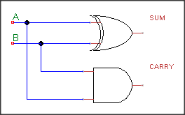
As you can see, this simple circuit is composed of two logic gates, XOR and AND. We simply XOR A and B to produce S, and AND A and B to produce C. Therefore, our F# definition for the half-bit adder is as follows:
let halfAdder (a,b) = (AND a b,XOR a b)
Which will result in a tuple (C,S). For the sake of testing this I have created a list of all the possible input pairs and a function that tests them against the half adder.
let trueFalsePairs = [(false,false);(true,false);(false,true);(true,true)]
let halfAdderTest =
    let toBin = function true -> 1y | false -> 0y
    printfn "A\t\tB\t\tC\t\tS\t\tBin"
    let testValue (a,b) =
        let (c,s) = halfAdder (a,b)
        printfn "%b\t%b\t%b\t%b\t%A" a b c s (sbyte(toBin c).ToString()+((toBin s).ToString()))
    trueFalsePairs |> List.iter testValue
This code results in the following output
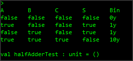
As you can see here, with no inputs the output is 0. When either A or B is 1 then the output is 1, and when both inputs are 1 then the output is 2 (10 in binary)
The Full Adder
The next circuit we will create is the FULL adder, which also has nothing to do with snakes or food. This circuit is capable of adding up three bits! First let's look at the schematic:

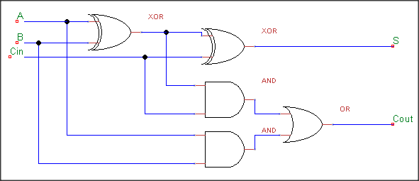
If you look carefully at this circuit, you will notice it is in fact two half-adders and an OR gate. The second half-adder takes its A input from the Sum output of the first half-adder and its B input from the carry-in bit. The carry-in bit is the (potential) carry-out bit from a previous adder, and in this way we can chain together adders to add up numbers of any size. This is called the ripple-carry adder which is slightly inefficient in electrical engineering terms but it is fine for what we will attempt to achieve next. Before getting ahead of our selves, let's implement the full, all-singng, all-dancing adder in its full venom injecting glory:
let fullAdder (a,b) c =
    let (c1,s1) = halfAdder (a,b)
    let (c2,s) = halfAdder (s1,c)
    (OR c1 c2,s)
Easy huh? Now, in order to test it, what I am not going to do is what I did before with the half-adder, by creating a list of all possible inputs and then creating some custom test code ...
Testing those blasted reptiles!
I can tell you now, as this article progresses we will want to be testing all kinds of circuits that will have a dynamic amount of inputs. For example, in the next part we will create the ability to dynamically create ripple carry adders based purely on the amount of inputs that you give them. Therefore it makes sense to write the common part of the algorithm and provide a way to supply the custom parts. In an OOP language we'd be all like "inheritance to the rescue!" (or use the strategy pattern perhaps - in fact, the solution I will use is pretty much identical to the strategy pattern but we use first-class functions and no concrete objects) however we are using a functional language so I won't be using inheritance. Instead, we will do this the functional way which is to provide the custom parts of the algorithm in (drumroll......) functions! In order to facilitate this, let's first think about what we are going to need to test our circuits.
- The ability to produce an exhaustive list of all possible combinations of true/false values for n number of bits.
- The ability to use either all of the above list or maybe only a random slice of the inputs, because we could be dealing with pretty big numbers
- Various helper functions that will make the output readable. These functions will be able to create binary and decimal representations of our boolean lists.
This will be the first cut of the testing stuff and we can improve on it later if need be. This isn't supposed to be the best framework on the planet or anything. The functions that each test will have to provide will be supplied via the following interface
type InputType = | All | Range of uint64
type TestTemplate =
    abstract member NumberOfBits : uint64
    abstract member Execute : (bool list -> unit)
    abstract member InputType : InputType.
Notice here that we are using 64bit unsigned integers all over - this is to allow us maximum flexibility to test larger 32bit numbers. We have defined a discriminated union InputType that will describe whether to take the whole potential input list or to take a random slice of it, and how bigger slice to take. The interface TestTemplate will make the magic happen. NumberOfBits is what the general algorithm will use to decide what list of inputs to create. Execute is the function that takes each set of inputs, executes the function(s) on it that we are trying to test and prints some output. Finally, InputType (as above) determines the range of the inputs to take, if not all of them. If this doesn't all make sense, it should do in a minute.
Now let's knock together some utility functions for handling our inputs and outputs. I will go through each one in turn.
let boolOfBin = function 0UL -> false | _ -> true
let binOfBool = function false -> 0UL | true -> 1UL
Two very simple functions that convert 0 and 1 into false and true, and vice versa.
let binOfInt input pad =
    let rec aux acc pad n =
        match n,pad with
        | 0UL,0UL -> acc
        | 0UL,pad -> aux (0UL::acc) (pad-1UL) 0UL
        | n,pad -> aux ((n&&&1UL)::acc) (pad-1UL) (n>>>1)
    aux [] pad input
This is a very useful function that will create a binary representation (in the way of a list of ints) of the passed in number. That is, passing in 4UL would result in [1UL;0UL;0UL]. It also has a pad parameter which will always ensure the list is of a certain length by way of Cons'ing a bunch of extra zeroes on the front of the list. This is very important because our circuits will expect a certain amount of bits, so we need to make sure we supply them even if they are all zero.
This conversion from integers to binary can be done in a bunch of different ways, what I have done here seemed most natural. All we are doing is ANDing the LSB of the input number with 1, adding the result to the accumulator, and then shifting the input along by one bit. We keep doing this until the input is equivalent to 0, at which point we are done, unless we still need to pad a few zeroes out. If you are not sure what's going on here you should brush up on your binary maths a little, it will help a lot with the coming stuff.
let stringOfList input =
    input
    |> List.fold( fun (acc:System.Text.StringBuilder) e -> acc.Append(e.ToString())) (System.Text.StringBuilder())
    |> fun sb -> sb.ToString()
This very simple code takes any list and converts it to a string by appending the result of calling ToString() on each element into a StringBuilder. We will use this for converting lists of integers (such as produced in the previous function) into readable strings like "01101".
let decOfBin input =
    Convert.ToUInt64(input,2).ToString()
This function takes a binary string input (like what is produced in the previous function) and convert it into a unsigned 64-bit integer. Simples.
let bitsOfBools = List.map toBin >> stringOfList
A function that will take a list of our booleans, convert them to binary, and finally produce a readable string from them.
let createInputs start max pad =
    [for x in start..max do yield binOfInt x pad]
And finally, our amazing input generating function. This guy takes a start and end number, plus a pad, and creates a list with a binary representation (in the form of another list, see the binOfInt function) of each number. For example, if you call createInputs 0 3UL 2UL the output will be :
[[0UL; 0UL]; [0UL; 1UL]; [1UL; 0UL]; [1UL; 1UL]]
Which you might recognise as the same input we used to fully-test the half adder circuit earlier.
Putting it all together
Ok, we have all of our utility functions defined, so let's go on to write the general test function algorithm :
let rnd = Random(DateTime.Now.Millisecond)
let test (template:TestTemplate) =
    let max = uint64(2.0**float(template.NumberOfBits)) - 1UL
    match template.InputType with
    | All -> createInputs 0UL max template.NumberOfBits
    | Range(n) -> let n = if n >= max then max else n
                  let start = uint64(rnd.NextDouble() * float(max-n))
                  createInputs start (start+n) template.NumberOfBits
    |> List.map (List.map boolOfBin)
    |> List.iter template.Execute
The test function accepts a parameter template which is an instance of the TestTemplate interface that we defined earlier. First, we declare a random number generator that will be used if the template has specified it would like to use a random range of its possible inputs. Then we establish the maximum possible number that the range could encompass - this is achieved by raising 2 to the power of whatever the requested number of bits is from the template, and subtracting one. (We subtract one because our binary numbers start at 0 not 1. The maximum number that will fit into a byte is 255, not 256, for example.) The results of this are then converted into the boolean format that our gates require and then each list is iteratively passed into the function Execute.
So let's define a test template that will test the half adder from earlier:
let testHalfAdder() =
    test
        { new TestTemplate with
            member x.InputType = All
            member x.NumberOfBits = 2UL
            member x.Execute = function
                | a::b::[] ->
                    let (c,s) = halfAdder (a, b)
                    printfn "%i\t%i\t%s" (binOfBool a) (binOfBool b) (stringOfList([binOfBool c;binOfBool s]))
                | _ -> failwith "incorrect inputs" }
In order to test the full adder, the template is almost identical. The only difference is the amount of inputs goes up to three (because we need a carry-bit), the actual function that executes, and a slight change to the output :
let testFullAdder() =
    test
        { new TestTemplate with
            member x.InputType = All
            member x.NumberOfBits = 3UL
            member x.Execute = function
                | a::b::c::[] ->
                    let (co,s) = fullAdder (a,b) c
                    printfn "%i\t%i\t%i\t%s" (binOfBool a) (binOfBool b) (binOfBool c) (stringOfList([binOfBool co;binOfBool s]))
                | _ -> failwith "incorrect inputs" }
Running these functions produces the following output :
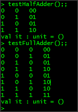
As you can see, every possible input is executed and the full adder is able to add up to three in binary (11) when all the inputs are high! AMAZING!
Ripple Carry Adders!
Right, now we have all the tools we need to easily test new circuits, so let's step it up a notch. As I mentioned earlier, a ripple-carry adder is a cool circuit that is essentially a bunch of adders in a sequence, with the carry-out bit being passed into the carry-in bit of the next adder. This allows us to add up numbers of any size! First let's have a look at the schematic (which I stole shamelessly from Wikipedia) :
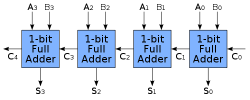
Important things to notice here - The circuit flows from right to left. The inputs to the adders are formed by taking the respective pair of inputs from each number we are trying to add up. Eg if we have A=1111 and B=0101, then the first adder's inputs will be (1,1), the second (1,0) the third (1,1) and the fourth (1,0). Notice here that the first adder takes a carry-in bit C0. This first adder can actually be replaced with a half-adder because we would not have a carry-in bit at the start of the circuit. In our code though we will simply use a full adder and always supply the initial carry-in bit as 0. My objective for the nAdder function is not to tell it how many adders to create, but rather drive this from the input it receives. This turns out to be fairly simple to do using recursion - the only thing we have to worry about is passing the carry-out bit of the previous full adder into the carry-in bit of the next adder:
let nAdder inputs =
    let rec aux c results = function
        | ab::xs ->
            let (c1,s) = fullAdder ab c
            aux c1 (s::results) xs
        | [] -> (results  , c)
    aux false [] inputs
Our nAdder implementation takes a list of inputs. It expects each item of the input list to be a tuple (an,bn) which will be passed along with the carry-in bit into our fullAdder function as defined earlier. The result of this (sn) is appended to an output list, and the function is then called recursively, passing along the cn bit into the next adder. When the inputs are exhausted, the final [s0...sn] list is returned along with the final carry-out bit from the last adder. Once again, the actual implementation of the circuit itself is very simple. The test template however is going to get much more complicated than the previous ones because we have to deal with any amount of inputs, and now we are taking two full binary numbers and adding them up as opposed to taking 2-3 individual bits and adding them up. I will show the template first and then go through it afterwards:
let testNBitAdder n =
    test
        { new TestTemplate with
            member x.NumberOfBits = (n*2UL)
            member x.InputType = Range(32UL)
            member x.Execute = fun input ->
                let rec buildInput acc = function
                    | a::b::xs  -> buildInput ((a,b)::acc) xs
                    | [] -> acc
                    | _ -> failwith "incorrect input"
                // exctract input and format the full A and B numbers ready for displaying
                let input = buildInput [] input
                let (A,B) = input |> List.unzip |> fun (A,B) -> (List.rev A |> bitsOfBools, List.rev B |> bitsOfBools )
                // perform the calculation and format result as a binary string
                let result = nAdder input false |> fun (out,c) -> (binOfBool c)::(List.map binOfBool out) |> stringOfList
                // print input number A, B and the result, all in binary
                printf "%s %s %s"  A B result
                // print it again in decimal to show the equivalent sum
                printfn " : %s + %s = %s"  (decOfBin A) (decOfBin B) (decOfBin result) }
First we declare the number of required bits to be 2*n. This is because if we ask for a 4-bit adder, that actually means we want to add two 4-bit numbers so our input space is 8 bits. We also set the input type to a range of up to 32 unique inputs - this is because we could generate huge sequences of inputs as we put in higher numbers, so we just want a random slice of those to test with. Next up is to build the input from the passed in sequences. This is a bit different to what we have done before. Because the input sequence generated will effectively be [a0;b0;a1;b1;..an;bn] we need to split this into the tuples (ab,bn) that our nAdder function is expecting. Once this is done, we use the List.unzip function on the resulting list of tuples to get us the full input numbers for A and B, which are then converted back to strings using List.rev and the bitsOfBools function so that we can show these in the output. Why are we using List.rev ? Because our input holds sequences starting from the LSB - to get the actual binary numbers we need to reverse the inputs.
Finally, we call nAdder using the list of input tuples and an initial carry-in bit of false. The results are then formatted so that the final carry-out bit forms the head of a results list where the tail is the output converted into binary. The whole thing is then transformed into a string ready for ouput. All that is left is the actual output itself, and because we are dealing with bigger numbers we give a decimal representation of the sum as well so you can easily see the ripple adder is functioning as intended. Here are some sample outputs from calling testNBitAdder with various sized inputs:
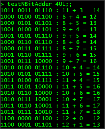
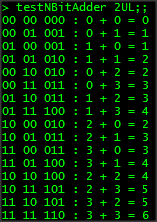
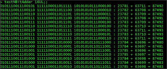

Wow! As you can see our little functions were bolted together, called recursively, and can add up numbers up to 32 bits! The first part of the article has already gone on longer than I expected. In the next part, I will continue from this point, and we will look at line-level decoders, multiplexers, and then we will take everything and produce a whole arithmetic logic unit that is capable of performing addition, OR and AND operations on n-bit numbers. The ALU is the core of the CPU so if you don't have any idea about how this stuff works, you are already well on the way! I have attached the source thus far should you wish to play around with it.
Logic1.fsx (5.28 kb)